Programming a robot fanuc system begins with understanding the task, the workcell, and the controller—not simply entering motion commands. This guide introduces the core steps: confirming the robot’s coordinate frames, teaching positions, building a program, and checking its behavior before production. A FANUC pendant, a clear view of the tool, and a carefully chosen starting point make the process easier to follow. Small details matter.
Robotics researcher Rodney Brooks wrote, “The world is its own best model.” That idea is useful here: a program must account for the real workcell, including fixtures, cables, tool offsets, and the part’s actual location. Simulation can help reveal problems, but it cannot replace cautious checks on the physical robot. A small mismatch between a taught point and the real setup can change the outcome.
The sections ahead explain common FANUC programming concepts in practical language, from motion instructions to program structure and troubleshooting. They also highlight safe habits, such as verifying the work area, using suitable speed settings during checks, and following site procedures. Exact screens and options can vary by controller and software version, so confirm details against the relevant FANUC documentation. This is not always a perfectly tidy process; careful observation and revision are part of good programming.
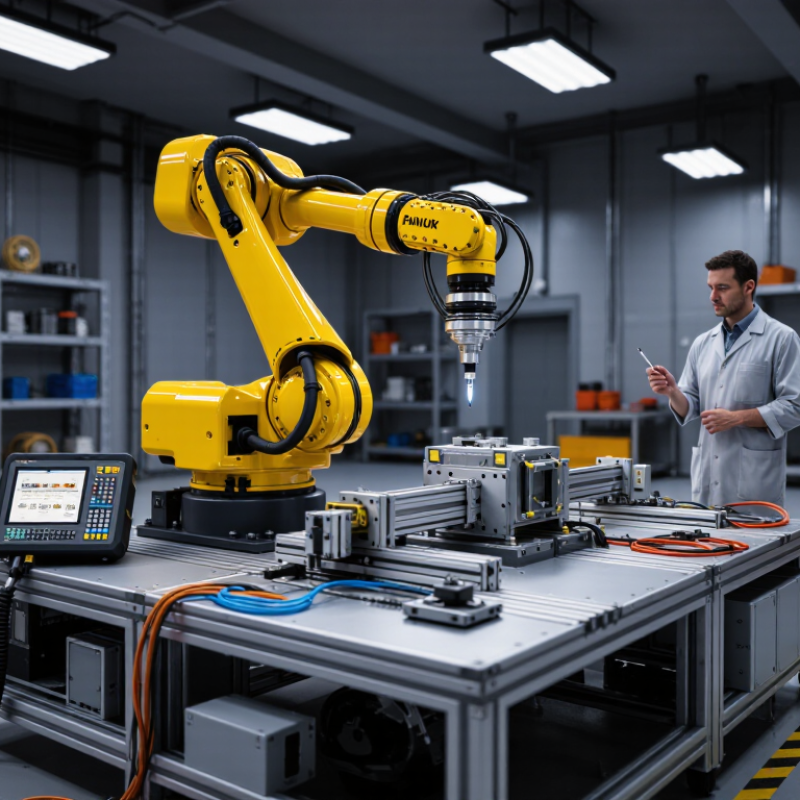
Robot programming begins with a clear description of the task: where a part starts, where it must go, and how the tool should approach it. Set the tool center point and work coordinate frame carefully; small errors can shift every taught position. Use the teach pendant to jog the arm at a reduced speed, then record simple points such as approach, pick, and retreat. Keep paths clear of fixtures and check payload settings before testing. Slow movements reveal mistakes sooner.
Tips: Label points by purpose, not just number. Keep the first test speed low. Confirm the emergency stop and safety zones work before motion begins.
A basic program often combines motion instructions, waits, and input or output signals. For example, the robot may move to a pick point, wait for a sensor, close a gripper, and then travel to a place point. Test each section separately, watching for unexpected rotations or awkward wrist movement. A dry run without a part can expose timing and clearance problems. Coordinate frames can be confusing at first, and even a tidy path may need revision after seeing the real cell. Record changes so another technician can understand why a point moved.
Example Cartesian teach-point coordinates for a simple pick-and-place sequence. X and Y positions are shown in millimeters; the values illustrate a sample workcell path and are not specifications for a particular robot.
Before programming, prepare the cell, not just the teach pendant. Confirm the robot’s mounting is secure and its reachable area is clear of fixtures, cables, and people. Check the tool, payload, and workpiece dimensions against the planned motion. Then define the tool center point and work coordinate frame carefully; a small offset can send a correct-looking path into a clamp. Small details matter. Keep the emergency stop accessible, verify protective devices, and use reduced speed while teaching. Follow the cell’s risk assessment and site procedures.
The scale of industrial automation makes disciplined setup essential. The International Federation of Robotics reported 541,302 industrial robots installed worldwide in 2023, with 4,281,585 units operating by year-end in World Robotics 2024. These figures describe a broad, growing field, not a guarantee that any individual cell is ready to run. Record the robot’s starting position, save a controller backup, and label frames and programs in plain language. Clear labels help another technician spot an incorrect frame before motion begins.
Build a small test program first: move to a safe point, approach the work slowly, and inspect clearance from several angles. Confirm each motion in teach mode before running the full sequence. A rushed setup can look productive, but it often hides assumptions about reach or tool orientation. I would not treat a simulation as proof; real cables sag, and fixtures may sit slightly out of place. Recheck after changes.
A teach pendant turns a robot’s motion into a sequence of clear instructions. Start by selecting the correct tool and coordinate frame, then jog the arm slowly toward its first position. Record each point only after checking the gripper, cable routing, and nearby fixtures. Add motion instructions between points, and set conservative speeds while developing the program. Small setup errors matter.
The International Federation of Robotics reported 4,281,585 industrial robots in operation worldwide in 2023, in its World Robotics 2024 report. Reliable programming begins with repeatable checks, not complicated code. Test the path without a workpiece, watching for unexpected wrist rotation or a tool that passes too close to a fixture. Then run a slow cycle and compare the actual pickup and release positions with the intended ones. A clean screen path can still be wrong.
Tips: Name points by task, such as “Pick_Approach,” rather than “Point_5.” Keep the pendant’s emergency stop accessible. Recheck payload settings after changing tooling. And leave time for a second review; I would not trust a first-pass program just because it runs once.
| Step | Stage | Teach Pendant Instruction | Typical Data or Setting | Verification |
|---|---|---|---|---|
| 1 | Prepare the workcell | Confirm the robot cell is clear, the workpiece and tooling are secured, and the required safety devices are operational before enabling motion. | Check the cell layout, tooling, fixtures, guards, and emergency-stop devices. | Keep personnel outside the safeguarded space during automatic operation. Follow the site’s approved lockout and safety procedures. |
| 2 | Select or create a program | Open the program screen, review the available programs, and create a new program using the controller’s supported naming rules. | Example program name: LOAD_CYCLE |
Confirm the intended program is selected and that existing production code will not be overwritten. |
| 3 | Set the coordinate frames | Review the active tool frame and user frame. Select the frames that match the installed end effector and workcell setup. | Tool frame: gripper reference; user frame: fixture or worktable reference. | Check frame selection and calibration against the cell documentation before teaching points. |
| 4 | Choose a motion mode | Use the pendant’s approved teach mode and select a suitable jog coordinate system, such as joint, world, tool, or user coordinates. | Use reduced speed while teaching; increase speed only during authorized testing. | Verify the displayed mode and speed override before moving the robot. |
| 5 | Jog to a safe approach point | Move the robot with the enabling device and jog controls to a clear position above or away from the work area. | Teach an approach point with clearance from fixtures and other equipment. | Use small movements near obstacles and monitor all robot axes and the end effector. |
| 6 | Teach the target position | Jog to the required work position and record the robot’s current position as a point instruction using the pendant’s position-recording function. | Example point labels: P_APPROACH and P_PICK. |
Confirm the recorded position, selected frames, and approach direction before continuing. |
| 7 | Add motion instructions | Insert point-to-point or linear motion instructions according to the path requirements. Use a linear path where the tool must follow a straight approach or retreat. | Point-to-point motion for general repositioning; linear motion for controlled straight-line travel. | Check that the selected motion type is appropriate for the tooling, clearance, and process. |
| 8 | Set speed and termination | Enter an appropriate speed and select how the robot should finish each motion, such as stopping at the point or blending through it. | Use conservative speeds for initial testing; use a full stop at critical process positions. | Review speed units and motion transitions. Blended motion may pass near, rather than exactly through, a taught point. |
| 9 | Add process I/O | Insert the required digital input or output instructions for gripper control, part detection, or process handshaking. | Example sequence: close gripper, wait for part confirmation, then retreat. | Confirm signal names, electrical behavior, and timing with the cell’s I/O documentation. |
| 10 | Review the program | Inspect the instruction sequence for correct points, motion types, speeds, frame selections, and I/O logic. | Check approach, process, retreat, and return-to-safe-position steps. | Resolve missing points, unintended jumps, and conflicting or incomplete I/O conditions. |
| 11 | Test at reduced speed | Run the program in the approved test mode at reduced speed, observing each motion and using the available pause or stop controls as needed. | Test one cycle at a time before considering normal production speed. | Watch for collisions, unexpected paths, incorrect gripping, and interference with fixtures or cables. |
| 12 | Validate and document | After authorized validation, record the program revision, frame data, tool setup, and any approved operating limits. | Document the date, tested cycle, and change description. | Pendant menus, instruction names, and available functions vary by controller configuration. Use the applicable operating manual and site procedures. |
Testing a robot program is where careful planning meets real motion. Start with a simulation or a controlled dry run, then use reduced speed in a clear work area. Keep people outside the safeguarded space and follow the cell’s approved operating procedures. Watch the tool, not just the screen. A cable that looks clear in a static pose may snag during a turn.
Check each taught point against the actual workpiece. Confirm the tool center point, approach direction, and grip before running a full cycle. I’ve found that a small offset can make a clean path unreliable. It is easy to blame the waypoint. Sometimes the fixture moved instead. Measure before changing coordinates.
Refine one thing at a time. If the arm hesitates near a corner, inspect the path, speed, and blend settings separately. Record cycle time, alarms, and observed clearances after each trial. Keep notes. They prevent guesswork on the next shift. Test variations with a qualified operator present, and restore the last verified version if a change causes unexpected motion. Not every improvement is worth keeping. A slightly slower cycle may be more repeatable and easier to maintain.
Before running a robot program, confirm that everyone is outside the safeguarded work area and that gates and interlocks function correctly. Keep the emergency stop accessible. In teach mode, use the permitted reduced speed and move the arm in small, deliberate steps. Check the tool, payload settings, and nearby fixtures; a few centimeters of unexpected reach can matter. Run the first cycle slowly, watching for collisions, cable snags, or motion that differs from the approved path. Stop if anything looks wrong. Do not defeat a guard or rely on someone else to notice a hazard.
Maintenance requires a different level of caution. Isolate electrical, pneumatic, and other stored energy sources according to site procedures before entering the work envelope. Verify isolation, rather than assuming a switch is enough. Inspect cables, connectors, fasteners, and tooling for wear or looseness, and record defects before returning the cell to service. Keep a current, verified program backup, and document edits with dates and clear revision notes. A checklist can feel repetitive. That is exactly when attention can slip. After a change, test motion at low speed with the area clear, then confirm the safety devices still respond as intended. If a procedure is unclear, pause and ask a qualified technician.